[Box-type Transformer] Box-type Transformer Model Installation Specifications for Box-type Transformer
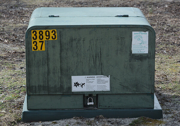
What are the types of box-type transformers
Among them, there are 10 domestic ones , 6, 3 and 0.4kV transmission and distribution system phasors also have two phases. In the Shanghai area, there is a 10kV and 110kV transmission system voltage phase difference of 60° electrical angle. At this time, a three-phase three-winding power transformer with a voltage ratio of 110/35/10kV and YN, yn0, y10 connection method can be used, but the use is limited. Three-phase three-core pillar type core.
Box-type transformer model: SCB10-100/10/0.4
Box-type transformer model: SCB10-160/10/0.4
Box-type transformer model: SCB10-200/10/0.4
Box-type transformer model: SCB10-250/10/0.4
Box-type transformer model: SCB10-315/10/0.4
Box-type transformer model: SCB10-400/10/0.4
Box-type transformer model: SCB10-500/10/0.4
Box-type transformer model: SCB10-630/10 /0.4
Box-type transformer model: SCB10-800/10/0.4
Box-type transformer model: SCB10-1000/10/0.4
Box-type transformer Model: SCB10-1250/10/0.4
Box-type transformer model: SCB10-1600/10/0.4
Box-type transformer model: SCB10-2000/10/0.4
Box-type transformer models There are two different phase angles for domestic transmission system voltages of 60 and 35kV. For example, the 220/60kV transformer uses YNd11 connection method, and the 220/69/10kV transformer uses YN, yn0, d11 connection method. The two 60kV transmission systems differ in electrical angle by 30°.
When the 220/110/35kV transformer adopts YN, yn0, d11 connection method, the 110/35/10kV transformer adopts YN, yn0, d11 connection method, the voltage phasors of the above two 35kV transmission systems also differ by 30° electrical angle.
Therefore, caution should be taken when deciding the connection method of the 60 and 35kV windings. The connection method must comply with the voltage phasor requirements of the transmission system. The connection methods of the 60 and 35kV level windings are determined based on the relative relationship of the voltage phasors. Otherwise, even if the capacity and voltage ratio are correct, the transformer cannot be used. If the connection method is incorrect, the transformer cannot be connected to the grid. But please note: when single-phase transformers are connected into a three-phase group, the three-phase group with YNy0 connection cannot be used. Three-phase shell-type transformers cannot use the YNy0 connection method.
Installation specifications for box-type transformers
1. Conditions that should be met for construction
(1) Joint review of drawings and preparation of detailed work instructions based on manufacturer’s information and approval.
(2) The quality of construction projects related to the installation of box-type transformers complies with the current national construction and acceptance standards.
(3) The positions of embedded parts and cable embedded pipes meet the design requirements, and the embedded parts are firm.
2. Construction preparation
2.1 Transformer foundation inspection
(1) Work with the owner and supervisor to check the construction quality of the transformer foundation Conduct inspections and fill out a record sheet, which will be signed and confirmed by all parties, and any problems discovered will be reported and dealt with in a timely manner.
(2) Carefully check the horizontal and vertical axis dimensions of the transformer foundation and the position of the embedded pipe, and check them with the dimensions given in the drawings. Only when they are correct can the next step be carried out.
2.2 Unpacking and inspection of transformer
(1) When unpacking and inspecting the transformer upon arrival, it should be inspected together with relevant personnel from the owner, supervisor and manufacturer.
(2) Measure and record the impact value of the impact recorder before unloading the truck. This value should be less than 3G.
(3) Check that there is no damage to the appearance of the transformer and that the paint surface is intact, and record it.
(4) Check that the components inside the transformer are not displaced or contaminated.
3. Install the transformer in place
(1) Install the transformer channel steel foundation on the embedded parts, pay attention to leveling and alignment, and the channel steel The foundation and embedded parts are welded firmly, and the welding parts are coated with anti-corrosion paint after removing the coating.
(2) After the fan is hoisted, the hoisting transformer is directly located on the foundation, and the jack is used for leveling and alignment.
(3) Connect the transformer to the foundation according to the fixing method (screw connection or welding) specified by the manufacturer.
(4) If the product arrives separately, install the outer casing after the transformer is installed and aligned.
(5) Hang signs and clean the inside of the transformer box.
(6) Finished product protection work must be done before the next process.
4. The cable line between the box transformer and the fan
The cable line between the wind turbine and the box transformer is laid in an underground cable trench, and it is laid between each fan and the box transformer. 1 YJY23-(3×240), 0.6/1kV and 1 YJY23-(4×240), 0.6/1kV cross-linked polyethylene insulated armored power cable. Cable head grounding: 1500m of 40mm2 copper glue wire (including cable intermediate joint). The bill of quantities is as follows:
(1)YJY23-3×240 26/35kV 240mm2 cable 16km;
(2)YJY23-3×95 26/35kV 95mm2 cable 14km;
(3)YJY23-3×50 26/35kV 50mm2 cable 5km;
(4)3 sets of 35kV cable terminals (YJY23-3×240 26/35kV);
(5) 58 sets of 35kV cable terminals (YJY23-3×50 26/35kV);
(6) 35kV cable intermediate joints (quantity determined according to cable supply length);
(7)YJY23-(3×240), 0.6/1kV 2100m;
(8)YJY23-(4×240), 0.6/1kV 2100m; 232 sets of 1kV cable nose. There are 58 box-type transformers; 47 cable branch boxes (including 8 4-cable terminals; 39 3-cable terminals).
5. Line retesting process
Due to the needs of the project, a combination of total station and GPS positioning system is used for retesting. Instrument observation and recording should be completed by two people respectively, and should be checked and verified on the same day of operation.
The line retest should be conducted in one direction. If it is conducted from both ends to the middle, the junction should exceed at least two C piles (one base tower). Check whether the central pile of the tower is stable and whether it is loose. If there is any looseness, fix it firmly first and then measure. For the tower piles that are re-tested and calibrated, clear and stable signs must be set up. For the construction boundary between the two construction units, they must be re-tested to the corner and beyond the two foundations. Only after contacting the other party to confirm that it is correct can the pits be separated. dig. When re-testing the construction, fill in the records in a timely manner, and the records must be true and accurate. If you encounter any discrepancies with the design during retesting, report it immediately and do not handle it yourself.
6. Crossing over power lines
Before construction, the technical person in charge should determine the intersection angle of the crossing point according to the cross-section diagram of the crossing point in the line construction drawing. , re-measure the height of the overhead ground wire of the uninterrupted power line to the ground at the intersection point, the height of the lower conductor to the ground at the intersection point, the width between the conductor edges, and the terrain conditions. Based on the retest results, a spanning construction plan is selected.
(1) When crossing uninterrupted power lines, before the wiring construction, the construction unit should apply in writing to the operating unit to “exit the reclosing” of the live line, and the uninterrupted crossing construction can only be carried out after the implementation. When a fault trips during construction, it is strictly prohibited to forcefully transmit power without obtaining the consent of the on-site command.
(2) During the erection of the span, the safety factor of the lifting tools and ground anchors near the anchorage should be increased by 20% to 40%.
(3) Grounding protection measures should be taken for the pay-off pulleys on the pole towers on adjacent sides of the spanning gear. Before crossing construction, all grounding devices must be installed and reliably connected to the tower.
(4) Wiring construction across uninterrupted power lines should be carried out in good weather. Operations should be stopped when encountering lightning, rain, snow, frost, fog, relative humidity greater than 85% or strong winds above level 5 . If the above situation is encountered during construction, the deployed nets and ropes should be safely protected.
(5) The over-the-wire rope must be dried before use, and its unit resistance must be measured with a 5000V megger.
(6) If the passing of all ropeway ropes and insulating pole fixed ropes is not completed on the same day, the passing ropes and lead ropes should be recovered and properly kept, and should not be left out in the open overnight.
(7) During the process of laying lead ropes and insulating ropes that are not completely separated from the live lines, operators such as pulling ropes and tying must wear insulating boots and insulating gloves when operating.
If the website content violates your rights, please contact us to delete it。


