Inverter installation requirements steps
1. Ambient temperature
Generally applicable in Work in an environment of -10℃-40℃ and humidity change below 90%. If the ambient temperature is higher than 40℃, the frequency converter should be derated by 5% for every 1℃ increase.
2. General requirements at the installation site
1) No corrosion, no flammable and explosive gases, and liquids.
2) No dust, floating fibers and metal particles.
3) The foundation and walls of the installation site should be solid and free of damage and vibration.
4) Avoid direct sunlight.
5) No electromagnetic interference.
3. Installation space and ventilation of the inverter
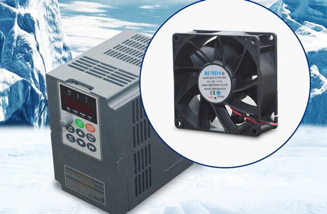
The inverter is equipped with a cooling fan to control For air cooling, in order to achieve good cooling circulation effect, the frequency converter must be installed vertically. When multiple frequency converters are installed in the same device or control box, it is recommended to install them horizontally in parallel to reduce mutual thermal effects.
4. Removal of the inverter cover
During installation, the inverter needs to be tested, inspected, wired, etc., which requires its cover to be removed. Pay attention to the characteristics of different frequency converters and install them according to their characteristics.
5. Inverter wiring
1) Check whether the wiring is correct.
2) Whether the wire shavings, especially metal shavings, short ends, screws, and nuts of the wires have fallen inside the inverter.
3) Whether the screw is tightened and whether the wire is loose.
4) Whether the exposed part of the terminal wiring collides with the live parts of other terminals or touches the inverter shell.
6. Precautions for control loop wiring
1) Wiring between the control loop and the main loop, and with other power sources Wire,Power lines should be routed separately and at a certain distance.
2) The relay contact terminal leads in the inverter control circuit should be routed separately from the connections to other control circuit terminals to avoid interference signals when the contacts are closed or opened.
3) In order to prevent the inverter from malfunctioning due to interference caused by noise and other signals, shielded wires are used in the control loop.
Installation and debugging of the frequency converter
1. No-load power-on test of the frequency converter
1) Connect the ground terminal of the frequency converter to the ground.
2) Connect the power input terminal of the frequency converter to the power supply through the leakage protection switch.
3) Check whether the factory display of the inverter display window is normal. If it is incorrect, it should be reset, otherwise it will be required to be returned.
4) Be familiar with the operating keys of the inverter. General inverters have six keys: RUN, STOP, PROG, DATAPENTER, increase (UP, ▲), and decrease (DOWN, “). Different inverter operations The definitions of the keys are basically the same. In addition, some inverters also have function keys such as MONITORPDISPLAY, RESET, JOG, and SHIFT.
2. No-load operation of the inverter with a motor
1) Set the power and number of poles of the motor, taking into account the operating current of the inverter.
2) Set the inverter The maximum output frequency, fundamental frequency, and set torque characteristics. General-purpose inverters are equipped with multiple VPf curves for users to choose. Users should choose the appropriate VPf curve according to the nature of the load when using it. If it is a fan or pump load, It is necessary to set the torque operation code of the frequency converter to variable torque and reduced torque operation characteristics. In order to improve the low-speed performance of the frequency converter when starting, so that the torque output by the motor can meet the requirements for starting production loads, the starting torque must be adjusted . In the asynchronous motor frequency conversion speed regulation system, the control of torque is more complicated. In the low frequency band, due to the influence of resistance and leakage reactance cannot be ignored, if VPf is still kept constant, the magnetic flux will decrease, thereby reducing the motor The output torque. For this reason, the voltage must be appropriately compensated in the low frequency band to increase the torque. Generally, the frequency converter is manually set by the user to compensate.
3) Set the frequency converter to its own In the keyboard operation mode, press the run key and stop key to observe whether the motor can start and stop normally.
4) Be familiar with the protection code when the inverter fails during operation, and observe the factory value of the thermal protection relay. Observe the setting value of the overload protection and modify it if necessary. The user of the frequency converter can set the electronic thermal relay function of the frequency converter according to the instruction manual of the frequency converter. When the output current of the frequency converter exceeds its allowable current, the frequency converter The over-current protection of the inverter will cut off the output of the inverter. Therefore, the inverter powerThe maximum threshold value of the sub-thermal relay does not exceed the maximum allowable output current of the inverter.
3. Trial operation with load
1) Manually operate the stop button on the inverter panel and observe the motor running stop process and the inverter display window , to see if there are any abnormalities.
2) If the inverter has an overcurrent protection action during the process of starting P and stopping the motor, the acceleration and deceleration time should be reset. The acceleration of the motor during acceleration and deceleration depends on the acceleration torque, while the frequency change rate of the inverter during starting and braking is set by the user. If the motor inertia or motor load changes, when accelerating or decelerating according to the preset frequency change rate, the acceleration torque may be insufficient, causing the motor to stall, that is, the motor speed is not coordinated with the inverter output frequency, resulting in excessive speed. current or overvoltage. Therefore, it is necessary to set the acceleration and deceleration time reasonably according to the motor’s moment of inertia and load, so that the frequency change rate of the inverter can be coordinated with the motor speed change rate.
Statement: The above content comes from the program system index or netizen sharing. It is for your reference only and does not represent the research views of this website. Please pay attention to the authenticity and authority of the source of the content. Apply for deletion >> Correction >>
If the website content violates your rights, please contact us to delete it。


