Inverter maintenance
Due to the rapid development of power electronics technology and microelectronics technology, the speed of inverter modification and replacement is also relatively fast, and new products are constantly being introduced. , performance continues to improve, and functions continue to be enriched and enhanced.
There are many inverter brands sold in the domestic market, such as Danfoss, ABB , SIEMENS, GE, Schneider, etc. , there are many domestic inverter brands. Although there are many types, their functions and uses are basically similar. Generally speaking, their use, maintenance and troubleshooting methods are basically the same.
In actual applications, the performance of the inverter will be affected by environmental conditions such as ambient temperature, humidity, vibration, dust, corrosive gases, etc., and its performance will undergo some changes. If used rationally and maintained properly, the service life can be extended and production losses caused by sudden failures can be reduced. If used improperly and the maintenance work cannot keep up, operating faults will occur, causing the inverter to fail to work normally, or even causing premature damage to the inverter, which will affect the normal operation of the production equipment. Therefore daily maintenance and regular inspection are essential.
1. Daily maintenance and inspection
For continuous operating frequency converters The operating status can be visually checked from the outside. Conduct regular inspections on the frequency converter to check whether there are any abnormalities when the frequency converter is running. Usually the following checks should be made:
(1)Whether the ambient temperature is normal, it is required to be within -10℃~+40℃ range, preferably around 25℃;
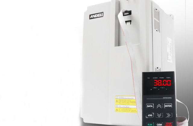
(2)Whether the output current, voltage, frequency and other data displayed by the inverter on the display panel are normal;
(3)Whether the characters displayed on the display panel are clear? Missing characters;
(4)Use a temperature measuring instrument to check whether the inverter is overheated and whether there is a peculiar smell;
(5)Is the inverter fan running normally? Is there any abnormality?Normally, whether the cooling air duct is smooth;
(6)Whether there is a fault alarm display during the operation of the inverter;
(7)Check whether the AC input voltage of the frequency converter exceeds the maximum value. The limit is 418V (380V×1.1). If the external input voltage of the main circuit exceeds the limit, even if the inverter does not Operation will also cause damage to the inverter circuit board.
2. Regular inspection
Use the annual overhaul time to focus the inspection on the parts of the inverter that cannot be inspected during daily operation.
(1)When performing regular inspections, the power must be cut off before operation. After the inverter is powered off, wait for 4min( after the power indicator light on the operation panel goes out. >The larger the capacity of the frequency converter, the longer the waiting time, the longest is15min) to fully discharge the DC filter capacitor of the main circuit. Use a multimeter to confirm that the capacitor is fully discharged. and then proceed.
(2)Remove the inverter control board and main board, and clean the inverter circuit board and interior with a brush and vacuum cleanerIGBTModules, input and output reactors and other parts. If the circuit board is dirty, wipe it off with a cotton cloth dipped in alcohol or a neutral chemical.
(3)Check the insulation of the internal wires of the inverter for signs of corrosion, overheating, discoloration or damage. If found, it should be processed or replaced in time.
(4)Due to vibration, temperature changes, etc., fastening parts such as screws often become loose in the inverter. All screws should be tightened once.
(5)Check whether the input and output reactors, transformers, etc. are overheated, discolored, burned, or smelly.
(6)Check the intermediate DC loop filter electrolytic capacitorCheck whether the small shoulder of the device (Safety Valve) bulges out, and whether there are cracks, leaks, or expansion on the outer surface wait. Under normal circumstances, the service life of filter capacitors is about 5 years, and the maximum inspection period is one year. When it is close to its life, the best inspection period is half a year. The capacity of the capacitor can be measured with a digital capacitance meter. When the capacity drops below 80% of the rated capacity, it should be replaced.
(7)Check whether the cooling fan is running intact. If there is any problem, replace it. The life of the cooling fan is limited by the bearings. The fan needs to be replaced once every 2–3 years depending on the operating conditions of the frequency converter. or bearings. If abnormal sounds or vibrations are found during inspection, they also need to be replaced.
(8)Check whether the insulation resistance of the inverter is within the normal range(All terminals and grounding terminals), be careful not to use a megger to measure the circuit board, otherwise it will damage the electronic components of the circuit board.
(9)Inverter’s R, S, T terminal and power cable are disconnected, U, V , W terminal and the motor end cable are disconnected, use a megohmmeter to measure the distance between each phase conductor of the cable and between each phase conductor and the protective ground. Whether the insulation resistance between them meets the requirements, it should be greater than 1MΩ normally.
(10)Before the inverter is put into operation after maintenance, it should be tested with the motor for a few minutes without load, and the direction of rotation of the motor should be calibrated.
3. The protection of the inverter itself
The inverter itself has Various protection functions, such as: load side grounding protection, short circuit protection, current limit, inverter overheating, overload, etc., and its self-diagnosisThe functions and alarm warning functions are also particularly perfect. Understanding these functions is very important for the correct use of the inverter and fault finding.
When the inverter is running, if current limit alarms or overcurrent protection occur frequently, you should check whether the load part and the inverterIGBT module are normal. If normal, then this The fault is that the Hall magnetic compensation current sensor on the main board of the frequency converter is damaged. Hall magnetic compensation current sensor is a kind of current value that measures sinusoidal and non-sinusoidal periods. It can truly reflect the waveform of the current and provide a control and protection signal for the frequency converter. Most of the components used in the inverter are products of the Swiss LEM company’s LA series. >LA series Hall magnetic compensation current sensors can be divided into three-terminal pins and five-terminal pins. The capacity of the inverter is different, and the specifications of the LA series Hall magnetic compensation current sensor on the motherboard are also different.
Production operations have shown that corrosive gases containing hydrogen sulfide at the viscose fiber production site will cause considerable harm to the electronic components of the inverter circuit board. We passed the test to the electrical control room Positive pressure fresh air is sent to improve environmental conditions, and Loctite electronic circuit board spray glue is used to treat the surface of the inverter circuit board with an anti-corrosion coating, which effectively reduces the failure rate of the inverter and increases its service life.
Electronic components are very sensitive to static electricity. If they are damaged by electrostatic discharge, they will cause soft breakdown. Soft breakdown will cause the circuit board to fail to work properly. Therefore, when replacing the circuit board, you must pay attention. Be sure to wear a grounding wristband before work, and connect the wristband directly to the ground to ensure that the human body is at zero potential to prevent static electricity from causing damage to the circuit board. If you don’t have a grounding bracelet, you can touch the metal shell of the inverter when replacing the circuit board to let the static electricity from the human body pass through the inverter shell(The metal shell conducts static electricity ). To ensure the safety of inverter circuit board spare parts, they should be stored in bags with anti-static materials during storage.
4A simple test method for the quality of components
In During the maintenance process, a multimeter should be used to detect the quality of electronic components according to the fault situation. If the measurement method is incorrect, it may lead to misjudgment, which will cause difficulties in the maintenance work and even cause unnecessary economic losses. The measurement methods are divided into two methods: component testing and circuit board on-the-road testing. On-the-road test: Disconnect the power supply of the inverter without disassembling the circuitUnder the conditions of board components, measure the components on the circuit board. For component breakdown, short circuit, and open circuit faults, this detection method can quickly and easily find damaged components, but the impact of the measured components on the circuit board and its parallel components on the measurement results should also be considered. , to avoid misjudgment errors. The following introduces how to judge the quality of components:
4.1Detection of ordinary diodes
Use MF47 multimeter to measure, connect the red and black test leads to both ends of the diode, read the reading, and then reverse the test leads to measure. Judging from the two measurement results, the forward resistance value of a low-power germanium diode is usually 300–500Ω , silicon diodes are about 1k Ω or more. The reverse resistance of the germanium tube is tens of kiloohms, and the reverse resistance of the silicon tube is above 500kΩ( The numerical values for power diodes are much smaller). A good diode has low forward resistance and large reverse resistance. The larger the difference between forward and reverse resistance, the better. If the measured forward and reverse resistances are both very small and close to zero, it means that the diode is short-circuited internally; if the forward and reverse resistances are very large or tend to infinity, it means that the tube is open-circuited internally. In both cases the diode needs to be scrapped.
On-circuit test: Test the forward and reverse resistance of the diodePN junction. It is easier to determine whether the diode has a breakdown short circuit or an open circuit.
4.2Transistor detection
Set the digital multimeter to the diode setting and use the test leads to measure the PN junction. If there is forward conduction, the displayed number is the PN junction. forward voltage drop.
First determine the collector and emitter; use a test lead to measure the forward voltage drop of the two PN junctions. The one with the larger voltage drop is the emitter. e, the smaller voltage drop is the collector c. When testing two knots,If the red test lead is connected to the common pole, the transistor under test is NPN type, and the red test lead is connected to the base b ; If the black test lead is connected to the common pole, the transistor under test is PNP type, and this pole is the baseb span>. After the transistor is damaged, the PN junction will suffer from breakdown, short circuit or open circuit.
On-road testing: On-road testing of transistors actually determines whether the transistor is damaged by testing the forward and reverse resistance of the PN junction. . The branch resistance is greater than the forward resistance of the PN junction. Normally, the measured forward and reverse resistances should be significantly different, otherwisePNPN span>The knot is damaged. When the branch resistance is less than the forward resistance of the PN junction, the branch should be disconnected, otherwise the quality of the transistor cannot be judged.
4.3Three-phase rectifier bridge module detection
With SEMIKRON(Siemens) Take the rectifier bridge module as an example. Set the digital multimeter to the diode test position, connect the black test lead to COM, and the red test lead to VΩ. , black and white test pens were measured 3, 4, 5 The forward and reverse diode characteristics between the 2 and 1 poles are used to check and judge the rectification Is the bridge in good condition? The bigger the difference between the measured forward and reverse characteristics, the better; if the forward and reverse characteristics are zero, it means that the detected phase has been broken down and short-circuited; if the forward and reverse characteristics are both infinite, it means that the detected phase has been open circuit. As long as one phase of the rectifier bridge module is damaged, it should be replaced.
4.4InverterIGBTModule Test
Set the digital multimeter to diode test file, test IGBTmodulesC1.E1, C2.E2 and between Gate G and E1, E2 The forward and reverse diode characteristics between the IGBT modules are judged whether they are intact.
Two red and black test leads are used to measure the grid G and the emitter E respectively. The forward and reverse characteristics between the two times, the values measured by the multimeter are both maximum, then it can be determined that the IGBT module gate is normal. If there is a numerical value displayed, the gate performance has deteriorated and the module should be replaced. When the forward and reverse test results are zero, it means that the detected one-phase gate has been broken down and short-circuited. When the gate is damaged, the voltage regulator tube used by the circuit board to protect the gate will also break down and be damaged.
4.5Detection of electrolytic capacitors
Usage When measuring with the span>MF47 multimeter, the appropriate range of the multimeter should be selected for electrolytic capacitors of different capacities. According to experience, under normal circumstances, electrolytic capacitors below 47μF can be used R×1K gear measurement, greater than 47μF electrolytic capacitors can be measured at the R×100 gear.
Connect the red test lead of the multimeter to the negative electrode of the capacitor, and the black test lead to the positive electrode. At the moment of contact, the multimeterThe pointer deflects to the right by a large margin, and then gradually turns to the left until it stops at a certain position(returns to the infinity position). The resistance at this time is the forward leakage resistance of the electrolytic capacitor. The larger this value is, the smaller the leakage current is and the better the performance of the capacitor is. Then, reverse the red and black test leads, and the multimeter pointer will repeat the above swing phenomenon. However, the resistance measured at this time is the reverse leakage resistance of the electrolytic capacitor, which is slightly smaller than the forward leakage resistance. That is, the reverse leakage current is larger than the forward leakage current. Practical experience shows that the leakage resistance of electrolytic capacitors should generally be above several hundred kiloohms, otherwise they will not work properly.
During the test, if there is no charging phenomenon in both the forward and reverse phases, that is, the needle does not move, it means that the capacitor capacity has disappeared or there is an internal short circuit; if the measured resistance value is very small or zero , indicating that the capacitor has large leakage or has been damaged by breakdown and can no longer be used.
On-road testing: On-road testing of electrolytic capacitors should only check for serious leakage or breakdown faults. The accuracy of testing electrolytic capacitors with slight leakage or small capacity is very poor. During on-road testing, the impact of other components on the test should also be considered, otherwise the values read will be inaccurate and affect normal judgment. Electrolytic capacitors can also use a capacitance meter to detect the capacitance value between the two ends to determine the quality of the electrolytic capacitor.
4.6Simple test of inductors and transformers
(1)Testing of inductors
Use MF47 type multimeter resistance range to test the resistance of the inductor . If the resistance of the inductor being measured is zero, it means there is a short circuit fault in the internal winding of the inductor. Note that the multimeter must be set to zero during operation and tested several times. If the resistance of the inductor being measured is infinite, it means that an open circuit fault has occurred at the contact point between the winding or the lead pin and the winding of the inductor.
(2)Simple test of transformer
Insulation Performance test: Use the multimeter resistance settingR×10K to measure the core and primary winding, primary winding and secondary winding, and core and secondary winding respectively. The resistance values between them should all be infinite. Otherwise, the insulation performance of the transformer is poor.
Measure winding continuity: use a multimeterR×1gear, measure the resistance value between the primary and secondary windings of the transformer respectively. Generally, the resistance value of the primary winding should be tens of ohms to hundreds of ohms. The smaller the power of the transformer, the greater the resistance value; the resistance value of the secondary winding is generally a few ohms to several ohms. Several hundred ohms, if the resistance value of a certain group is infinite, then the group has an open circuit fault.
Note: This measurement method is only a rough estimate. Some transformers with slight short circuits in the insulation between winding turns cannot be detected accurately.
4.7Simple test of resistor resistance
Shut off when measuring resistance on the road For circuit board power supplies, the impact of other components in the circuit on the resistance value must be considered. If a capacitor is connected to the circuit, the capacitor must also be discharged. The multimeter needle should point at the center of the scale for accurate readings.
4.8SMD components
(1)Types of SMD components
Most inverter electronic circuit boards now use SMD components, also known as surface assembly Component, which is a micro-miniature electronic component with no leads or very short leads and suitable for surface assembly. There are many varieties and specifications of chip components, which can be divided into rectangular, cylindrical and special-shaped structures according to their shapes. According to type, they can be divided into chip resistors, chip capacitors, chip inductors, and chip semiconductor devices(Can be divided into chip diodes and chip transistors), chip integrated circuit.
(2)Disassembly and soldering of SMD components
Use35W internal heating electric soldering iron, equipped with long-life oxidation-resistant tip soldering iron tip. Wipe off the residue on the soldering iron tip, leaving only a thin layer of solder. It is relatively easy to disassemble and weld the SMD components at both ends. SMD integrated circuits have thin and numerous pins, small pin spacing, and compact arrangement of surrounding components, making them difficult to disassemble and assemble. Their disassembly and welding are difficult without special tools. Here we focus on the disassembly and welding operations of chip-type integrated circuits.
(3)Disassembly method
If the integrated circuit has been identified If the block is damaged, use a paper cutter to cut off the pins completely and remove theLower the integrated circuit block. Be careful not to cut the blade into the circuit board when cutting. Then, use tweezers to hold the broken legs, use a pointed soldering iron to melt the solder on the broken legs, and remove the broken legs one by one.
(4)Welding method
Before welding, use alcohol to Remove the excess solder and dirt on the circuit board copper of the integrated circuit block, clean it, apply alcohol and rosin water to the pins of the integrated circuit block, and coat the pins with a thin layer of tin. Then, check the pin positions of the integrated circuit, place the integrated circuit block on the circuit board to be soldered, press the integrated circuit block lightly, use a soldering iron to solder the pins on the four corners of the integrated circuit block first, and fix the integrated circuit block. Okay, let’s solder the other pins one by one. In order to ensure the welding quality, it is best to use thinner solder wire, such as 0.6mm solder wire, for better welding effect.
Statement: The above content is provided by the program system index or shared by netizens. It is for your reference only and does not represent the research views of this website. Please pay attention to the authenticity and authority of the source of the content. . Apply for deletion >> Correction >>
If the website content violates your rights, please contact us to delete it。


