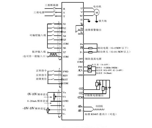
Inverter wiring diagram
The following picture is an inverter wiring diagram. There are some issues that need attention during the installation of the frequency converter. For example, the frequency converter itself has strong electromagnetic interference, which will interfere with the work of some equipment, so we can add a cable sleeve to the output cable of the frequency converter. Or the control line in the frequency converter or control cabinet should be at least 100mm away from the power cable, etc.
Basic composition of the inverter

Inverter wiring method
Main circuit wiring

1. The power supply should be connected to the input end of the inverterR,S, T wiring terminals must not be connected to the output end of the inverter ( U, V, W), otherwise the inverter will be damaged. After wiring, loose thread ends must be removed. Fragmented thread ends may cause abnormalities, malfunctions and malfunctions. The inverter must always be kept clean. When drilling holes in the console, be careful not to allow debris, powder, etc. to enter the inverter.
2, at terminal+, PR, do not connect anything other than the recommended brake resistor option, or absolutely do not short-circuit.
3. Electromagnetic wave interference. The input/output (main circuit) of the frequency converter contains harmonic components, which may interfere with communication equipment near the frequency converter. Therefore, install the option radio noise filter FR-BIF or FRBSF01 or FR-BLFLine noise filter minimizes interference.
4. When wiring over long distances, due to the influence of the charging current of the parasitic capacitance of the wiring, the fast response current limiting function will be reduced, and the instrument connected to the secondary side will malfunction. and cause malfunction. Therefore, the maximum wiring length must be less than the specified value. When the wiring length must be exceeded, the Pr. 156 is set to 1.
5. Do not install power capacitors, surge suppressors and radio noise filters on the output side of the inverter. Otherwise, it will cause the inverter to malfunction or the capacitor and surge suppressor to be damaged.
6. In order to keep the voltage drop within 2%, appropriate types of wires should be used for wiring. When the wiring distance between the inverter and the motor is long, especially in the case of low-frequency output, the voltage of the main circuit cable will drop, causing the motor’s torque to drop.
7. After operation, the operation of changing the wiring must be done after the power is cut off for more than 10min and after checking the voltage with a multimeter. conduct. For a period of time after a power outage, dangerous high-voltage electricity remains on the capacitor.
Control circuit wiring

1. The wiring of control circuit terminals should use shielded wires or Twisted pair wire, and must be wired separately from the main circuit, strong current circuit, relay program circuit).
2. Since the frequency input signal of the control circuit is a small current, in the case of contact input, in order to prevent poor contact, the small signal contact should use two parallel nodes or use twin contact.
3. The wiring of the control loop generally uses 0.3~0.75 Sqm of cable.
Ground wiring

1. Due to leakage current in the inverter, in order to To prevent electric shock, the inverter and motor must be grounded.
2, dedicated grounding terminal for grounding the inverter. To connect the ground wire, use tinned crimp terminals. When tightening the screws, be careful not to break the turnbuckle.
3. Tin plating does not contain lead.
4. The diameter of the grounding cable should be as thick as possible, which must be equal to or larger than the specified standard. The grounding point should be as close to the inverter as possible. The shorter the grounding wire, the better.
If the website content violates your rights, please contact us to delete it。


