1. Principle of three-phase voltage regulator
The three-phase voltage regulator is an adjustable autotransformer that can be used as a stepless smoothing device to drive three-phase loads. Voltage regulating equipment, also known as thyristor power regulator, thyristor power regulator or simply power regulator.
The working principle of the three-phase voltage regulator is to connect a four-layer three-terminal semiconductor device between the power supply and the load, and with the corresponding trigger control circuit board, it can be adjusted to the load voltage, current and power. It is mainly used to adjust the heating power of various electric heating devices. It can be adjusted “manually” or cooperated with electric adjustment instruments, intelligent adjustment instruments, PLC and computer control systems to achieve constant value or program control of the heating temperature.
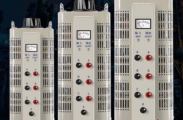
Two and three-phase voltage regulator wiring methods
The A, B, and C terminals of the three-phase voltage regulator are the input terminals, the a, b, and c terminals are the output terminals, and the 0 terminal is the star (Y-shaped) neutral point.
Generally speaking, the input wires are relatively fixed, so all three phases and four wires are connected. The output terminal depends on the load. If the three phases are balanced (such as motors, etc.) or when delta connection is required, 0 does not need to be connected. Otherwise, the 0 line must be connected.
The grounding wire must be connected according to regulations, and there is no need to separate the grounding.
Three-phase voltage regulator operation precautions
1. When doing high-voltage tests, 2 or more people must participate, and There should be a clear division of labor, clear communication methods, and dedicated personnel to monitor site safety and observe the test status of the test products.
2. The three-phase voltage regulator and control box should be reliably grounded.
3. During the test, the voltage boost speed cannot be too fast, and sudden full voltage power-on or power-off is never allowed.
4. During the voltage boosting or withstand voltage test, if the following abnormal conditions are found, the voltage should be reduced immediately, the power supply should be cut off, the test should be stopped, and the cause should be found out before testing again. ①The voltmeter pointer swings greatly. ② Found the smell of burnt insulation and smoke. ③There is abnormal sound in the product being tested.
5. During the test, if the test product is short-circuited or breaks down, the overcurrent relay in the control box of the oil-immersed high-voltage test transformer operates. At this time, return the voltage regulator to the zero position and cut off The test sample can be taken out only after the power is turned on.
6. When performing a capacitance test or a DC high-voltage leakage test, after the test is completed, lower the voltage regulator to zero and cut off the power supply. Then, use a discharge rod to connect the high-voltage end of the test sample or capacitor to the Discharge to the ground to avoid the risk of electric shock caused by the potential remaining in the capacitor.
If the website content violates your rights, please contact us to delete it。


